ARTIGO ORIGINAL
SIXTO, Luis Daniel Tamayo [1], ABREU, Daniel Cabezas [2], CARDENTEY, José Carlos Gálvez [3], LABRADA, Víctor Mir [4], HERNÁNDEZ, Yusdel Díaz [5]
SIXTO, Luis Daniel Tamayo et al. Numerical study of trapezoidal thread spindle for a mini lathe by numerical control. Revista Científica Multidisciplinar Núcleo do Conhecimento. Year. 10, Ed. 02, Vol. 01, pp. 05-22. February 2025. ISSN: 2448-0959, Access link: https://www.nucleodoconhecimento.com.br/mechanical-engineering/numerical-study-of-trapezoidal, DOI: 10.32749/nucleodoconhecimento.com.br/mechanical-engineering/numerical-study-of-trapezoidal
ABSTRACT
The objective of the work was to carry out a numerical and technological study of a trapezoidal thread spindle for a CNC (Computerized Numerical Control) mini lathe. A material with the necessary mechanical properties was selected to enhance the characteristics of the spindle. The geometric parameters of the 3D modeling were obtained from a previous analytical model. In the modeling and simulation using the finite element method, only the mechanical field was considered. The results obtained showed that a rigid design was generated that allows the combination of loads to which the trapezoidal thread spindle is subjected under its working conditions to resist.
Keywords: Mini-Cnc Machine, Lead Screw, Trapezoidal Thread, Finite Elements.
- INTRODUCTION
CNC mini machine tools are specially designed to be used in laboratories, small industries or for learning in universities. They are mainly used to manufacture small components, prototypes, and complex parts. The use of small CNC machine tools makes it possible to work with cost-effective precision equipment that provides space and electricity savings. In addition, it has several advantages, among which we can highlight: its high work flexibility and easy relocation, the reduction of vibrations and noise (Zhou and Pan, 2022) and (Ali and Mohsin, 2021).
The need for optimal productivity and tight part tolerances requires machine tools to be equipped with precise feed drives. In the context of small CNC machine tools, spindles play a fundamental role in power transmission and are used by various authors in their designs (Tung, Quynh, Quynh, 2021) and (Tung, Tan, Minh, 2023). In this case of trapezoidal thread screws, they are widely used due to their various specific advantages, among which their simple configuration stands out, making them easy to manufacture and less expensive than other power transmission mechanisms such as ball screws. From a design perspective, trapezoidal threads are thick at the root, allowing for high load-bearing capacity efficiently. They require little maintenance and provide limited design freedom. If properly lubricated, the trapezoidal spindle can provide quiet operation (Syriac and Chiddarwar, 2019) and (Wojtkowiak, Talaṥka Konecki, 2021).
About trapezoidal thread power screws, several authors have carried out studies to analyze the distribution of forces and stresses. Proskuriakov, Lopa, Trapeznikov (2017) established an analytical relationship between screw bending and moment of inertia in the cross-section. Syriac and Chiddarwar (2019) studied the effect of spindle parameter change on the system’s natural frequency and stress distribution. Also, other authors have carried out studies to obtain the effects of the thread parameter on the transmission efficiency. Cojocaru and Korka (2014) performed a finite element analysis of threaded screws with different diameters of trapezoidal and square thread profiles. Wojtkowiak, Talaṥka, Konecki (2021) presented a methodology for the optimization of the spindle drive mechanism using the Isight software. Ristivojević, Dimić, Kolarević (2023) conducted a study to analyze the effects of coefficient of friction and geometric and kinematic parameters on the energy efficiency of trapezoidal and metric threaded joints. On the other hand, authors such as Song and Wang (2018) analyzed in detail the CNC processing of trapezoidal threads.
The aim of this work is to carry out a numerical and technological study of a trapezoidal thread spindle for a mini-CNC lathe. The fundamental problem lies in the limitation of existing resources, so it is sought through the design and selection of the material to obtain a feasible solution. To carry it out, the use of Computer Aided Design (CAD) software is considered as a fundamental aspect, for 3D modeling and stress analysis using the finite element method. The parameters to be introduced into the software are obtained from a previous analytical design.
- MATERIALS AND METHODS
Se selecciona como material a utilizar el acero al carbono AISI 1045 por ser ampliamente utilizado en la fabricación del husillo trapezoidal. En la tabla 1 se muestran la composición química y las propiedades mecánicas de dicho acero.
Table 1. Chemical and mechanical properties of AISI 1045 steel
| Chemical Composition | |||||
| %C | %Fe | %Mn | %P | %S | |
| 0.42-0.50 | 98.51-98.98 | 0.60-0.90 | 0.04 | 0.05 | |
| Mechanical Properties | |||||
| Maximum Tensile Strength (MPa) | 565 | ||||
| Tensile yield limit (MPa) | 310 | ||||
| Elastic Modulus (GPa) | 200 | ||||
| Poisson’s coefficient | 0.29 | ||||
| Hardness (HB) | 163 | ||||
Source: Zaman et al. (2022).
2.1. TRAPEZOIDAL SPINDLE ANALYTICAL MODEL
The characteristic dimensions of the threaded spindle transmission are determined based on the wear check on the spindle-nut pair (Figueroa et al, 2023). The preliminary value of the average thread diameter is defined by the Eq. (1).
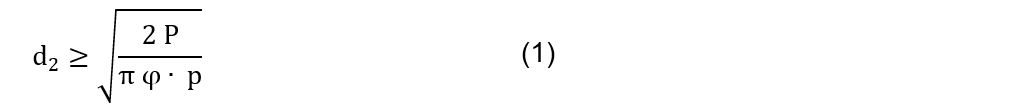
Where φ is the nut height coefficient and (p) is the average allowable specific pressure. P represents the sum of all axial loads acting on the normal area of the thread and is determined by Eq. (2).

In this expression, ![]() represents the feed force during turning,
represents the feed force during turning, ![]() is the coefficient of friction of the carriage with the bed, m is the mass of the tool carriage to be moved and the gravity component.
is the coefficient of friction of the carriage with the bed, m is the mass of the tool carriage to be moved and the gravity component.
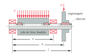
Figure 1. Cutting parameters and conditions during turning
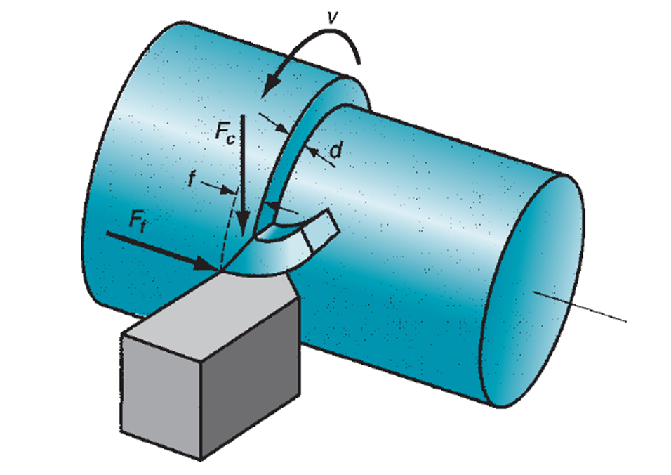
As can be seen in Fig. 1, the ![]() is perpendicular to the shear force
is perpendicular to the shear force ![]() . Both forces are associated with the shear strength of the working material and through equations can be related to each other. The
. Both forces are associated with the shear strength of the working material and through equations can be related to each other. The ![]() is defined by the Eq. (3).
is defined by the Eq. (3).

Where ![]() It’s friction angle and angle of attack of the tool
It’s friction angle and angle of attack of the tool ![]() . The Angle
. The Angle ![]() it is obtained by Eq. (4) From the coefficient of friction between the tool and the chip
it is obtained by Eq. (4) From the coefficient of friction between the tool and the chip ![]() .
.

The ![]() it is determined by the Eq. (5) From the specific energy of material U, the breakthrough f and the depth of cut d. The value of U It provides a useful measure of the amount of energy to remove a unit volume of metal during machining. In this case, the working material with the highest energy requirements that can be machined is aluminum.
it is determined by the Eq. (5) From the specific energy of material U, the breakthrough f and the depth of cut d. The value of U It provides a useful measure of the amount of energy to remove a unit volume of metal during machining. In this case, the working material with the highest energy requirements that can be machined is aluminum.

To determine the geometrical parameters of the trapezoidal spindle, the outer diameter of the thread is first defined, which is obtained by Eq. (6).

By consensus of authors, the value ![]() of the outer diameter is normalized to an oversized value mm, to ensure rigidity during the machining process and facilitate manufacturing. The rest of the geometric parameters of the trapezoidal thread to be determined are:
of the outer diameter is normalized to an oversized value mm, to ensure rigidity during the machining process and facilitate manufacturing. The rest of the geometric parameters of the trapezoidal thread to be determined are: ![]() average thread diameter, h1 height of the tooth profile, d3 thread bottom diameter, b width of the root of the screw fillet, and are defined by the Eq. (7), (8), (9) y (10) respectively.
average thread diameter, h1 height of the tooth profile, d3 thread bottom diameter, b width of the root of the screw fillet, and are defined by the Eq. (7), (8), (9) y (10) respectively.
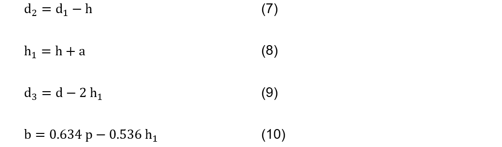
Where is the top clearance between the nut and h is the working height of the tooth profile that is equal to half the pitch .
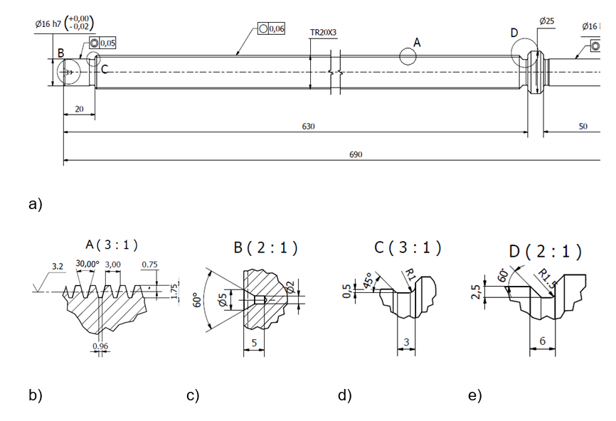
Figure 2 shows graphically the dimensions and geometric parameters of the trapezoidal spindle that were obtained by analytical modeling. Fig. 2 (b) shows a view of the threaded section where the geometric parameters of the trapezoidal thread are defined.
Figure 2. Dimensions and geometric parameters of the trapezoidal spindle, a) trapezoidal thread spindle, b) thread section view, c) center section view, d) thread outlet slot section view, e) thread start section view
In the case of the trapezoidal thread, the normal load of the thread is inclined towards the axis by an amount θ that is equal to half the angle of the thread. The effect of this angle θ increases the frictional force due to the wedging action of the threads (Budynas, 2014). The torsional moment required to overcome friction and move the load of the screw is obtained by Eq. (11).
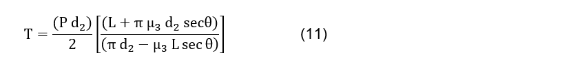
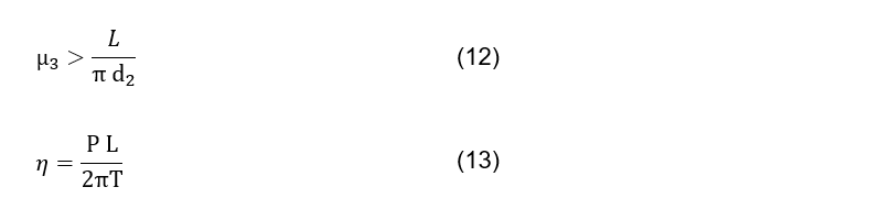
Where L is the thread feed and ![]() is the coefficient of friction between the nut and the screw. Eq. (12) and (13) define the self-locking condition and the efficiency of the spindle drive.
is the coefficient of friction between the nut and the screw. Eq. (12) and (13) define the self-locking condition and the efficiency of the spindle drive.
The maximum torque to which the spindle is subjected is that of the motor. This is obtained through Eq. (14).

Where N is the engine power and w are the rotational speed of the motor.
Table 2 shows the values of the coefficients and variables that were used in the equations for the formation of the analytical model.
Table 2. Coefficients and variables used for the calculation of the analytical design of the trapezoidal thread
| Coeficientes y variables | Valores |
| 2 | |
| (MPa) | 12 |
| 1.2 | |
| (kg) | 6 |
| 9,8 | |
| 0° | |
| 0.18 | |
| (N/m ) | 800 |
| (mm) | 0.4 |
| (mm) | 2 |
| (mm) | 0.25 |
| (mm) | 3 |
| Ángulo de la rosca | 30° |
| (mm) | 3 |
| 0.22 | |
| N (W) | 40 |
| w (rad/s) | 4.18 |
Source: Authors (2024).
2.1.1. STABILITY CHECKS OF THE TRAPEZOIDAL SPINDLE
Because the length of the spindle is eight times greater than the bottom diameter, the stability check against the longitudinal bending must be performed. Stability is evaluated based on the critical compressive force or compressive stress, based on the ratio of the spindle slenderness to the limit slenderness value that is set by the bearing conditions and geometry. The slenderness and limit slenderness values are obtained using the Eq. (15) and (16) respectively.
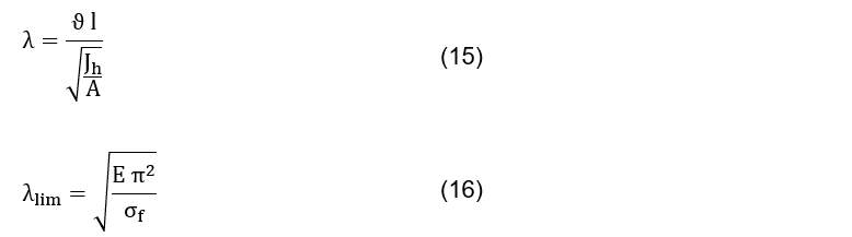
Where ϑ=1 is the coefficient of support, l the length of the spindle, ![]() is the moment of inertia of the spindle, A is the cross-sectional area of the solid spindle, E is the elastic modulus of the selected material and
is the moment of inertia of the spindle, A is the cross-sectional area of the solid spindle, E is the elastic modulus of the selected material and ![]() is the creep stress of the selected material. The geometric parameters of the moment of inertia and spindle area are obtained by equations (17) and (18) respectively.
is the creep stress of the selected material. The geometric parameters of the moment of inertia and spindle area are obtained by equations (17) and (18) respectively.
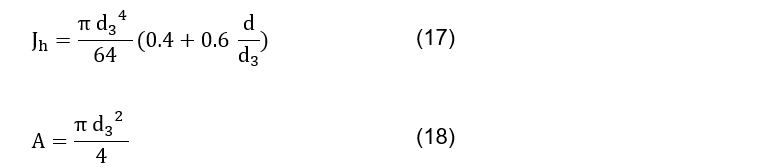
Table 3 shows the slenderness and limit slenderness values obtained.
Table 3. Calculated slenderness and slenderness limit values
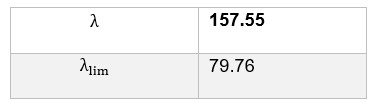
Source: Authors (2024).
Because the slenderness value is higher than the limit slenderness, the spindle is tested at critical compressive strength using equation (19).

2.2. MESHING
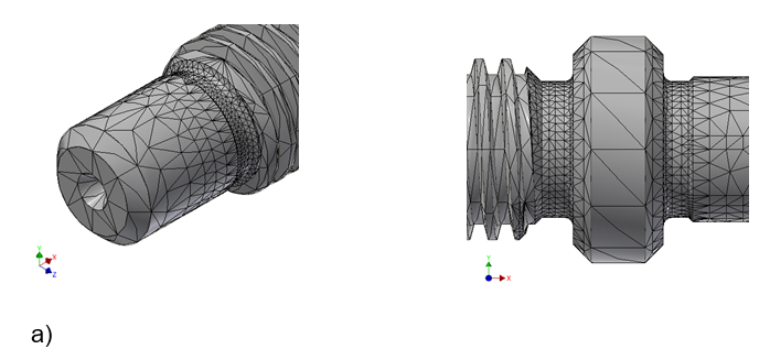
Tetrahedral elements with an average element size of 0.1 as a fraction of the length and a minimum element size of 0.2 as a fraction of the average size were used for meshing. A modification factor of 1.5 was used and curved mesh elements were created. A special mesh control with 1 mm elements was defined for the sections of the grinding and thread outlet slots, as they were the area’s most likely to be subjected to the greatest stresses, as shown in Figure 3. To determine the appropriate number of elements and nodes of the mesh, a convergence analysis was used, taking the Von-Mises stresses as a control parameter. An error of less than 1% between two consecutive results and a refining threshold of 75% was defined as a stopping criterion. Analysis was performed for all geometry.
Figure 3. Mesh control on the trapezoidal spindle, a) end support, b) coupling end support with the motor
2.3. MECHANICAL SIMULATION
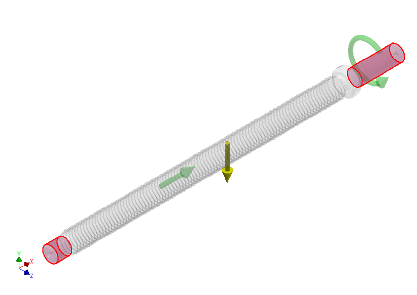
Figure 4 shows the 3D model generated in the CAD software with the boundary conditions and applied loads. As boundary conditions, the movement in the spindle supports was limited with tangential and axial constraints (in red). Regarding the load conditions, the torsional moment generated by the motor was applied at the end where it engages with the spindle and on the normal area of the thread an axial force that represents the sum of the axial loads. The values of both charges were obtained from the previous analytical model and are represented by green glyphs. To obtain a simulation as close as possible to the real working conditions of the spindle, it was decided to define gravity, which is represented by a yellow glyph.
Figure 4. 3D model of the trapezoidal spindle with the boundary conditions and applied loads
To carry out the analysis of deformations and stresses, it was assumed that the part behaves in an elastic, linear, isotropic, and homogeneous way. The resulting deformation that characterizes this type of behavior is given by Hooke’s Generalized Law, which is defined by the system of equations (20).
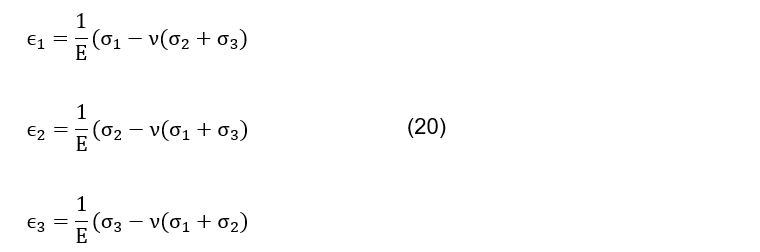
Where ![]() are the deformations as a function of the principal axes, is the Poisson coefficient, and
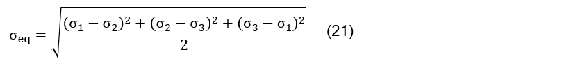
are the deformations as a function of the principal axes, is the Poisson coefficient, and ![]() are the main efforts. The equivalent von Mises stress constitutes a magnitude proportional to the strain energy and can be obtained through the principal stresses by Eq. (21).
are the main efforts. The equivalent von Mises stress constitutes a magnitude proportional to the strain energy and can be obtained through the principal stresses by Eq. (21).
3. RESULTS AND DISCUSSION
A proper mesh balances accuracy and calculation time. Figure 5 shows the plot of the convergence analysis obtained, where a total of 5 refining processes were needed to achieve a convergence rate of less than 1%. As a result of the analysis carried out, a mesh of 36565 elements and 64879 nodes was obtained.
Figure 5. Plotting the convergence analysis
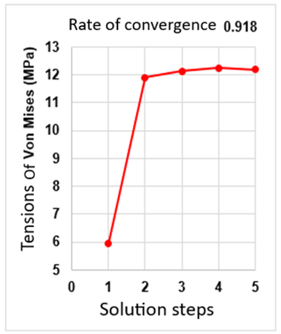
Figure 6 shows the behavior of von Mises stresses in the trapezoidal spindle. The highest stress values are obtained in the grinding groove and thread outlet at the end of the spindle (Figures 6 (b) and 6 (c)). These results are logical, since these areas have smaller dimensions and changes in cross-sections, so they are prone to be stress concentrators. The highest Von Mises stresses that can be seen are 12.19 MPa. Outside of the areas specified above, it can be observed that Von Mises stress values are observed in the groove at the beginning of the threaded zone, where values greater than 10 MPa are not reached. In all other regions of the trapezoidal spindle, practically zero values are shown.
Figure 6. Behavior of the Von Mises Stress in the trapezoidal spindle, a) trapezoidal spindle, b) coupling support with the motor, c) end support
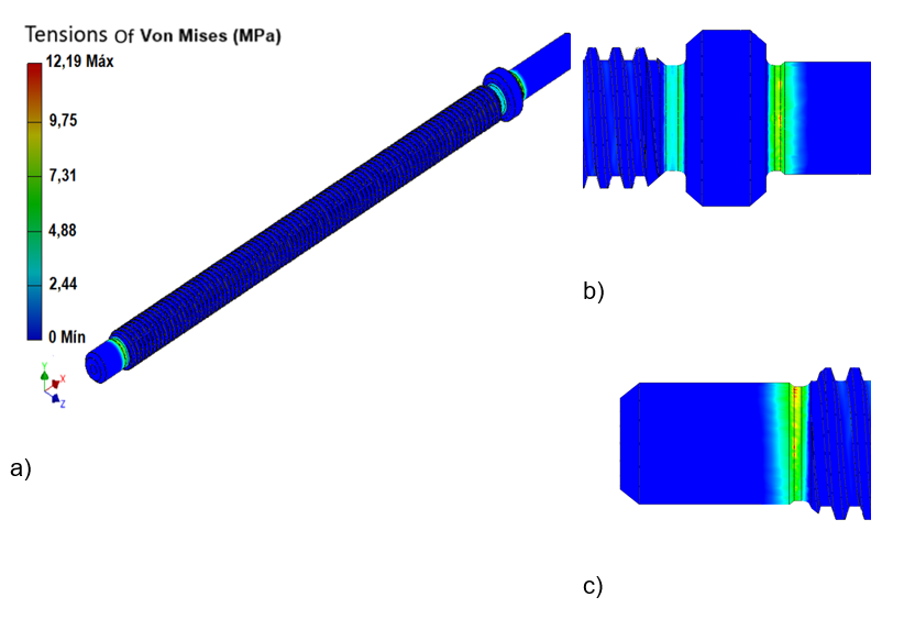
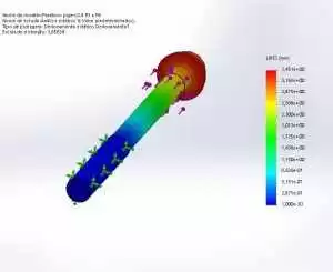
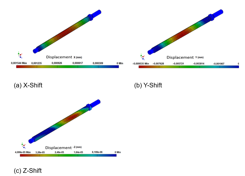
Figure 7 shows the behavior of the offsets in the trapezoidal spindle for the three coordinate axes. For each of the coordinate axes, the highest displacement values are in the middle part of the threaded zone. This behavior is justified by the axial force acting on the spindle, which causes it to behave like a column trying to buckle. The highest displacement values are obtained on the Y-axis (Figure 7(b)) with a value of 0.009535 mm, followed by the X axis (Figure 7(a)) with 0.001544 mm and the Z axis (Figure 7(c)) with ![]() mm. On the X-axis is where it is observed that the displacement values extend over a larger area of the screw, occupying a large part of the threaded area. All these displacement values are very small, so it can be said that the design made is practically deformed.
mm. On the X-axis is where it is observed that the displacement values extend over a larger area of the screw, occupying a large part of the threaded area. All these displacement values are very small, so it can be said that the design made is practically deformed.
Figure 7. Behavior of the displacements in the trapezoidal spindle on the three coordinate axes, X-axis displacement a), Y-axis displacement b) and Z-axis displacement c)
4. FINAL THOUGHTS
The analytical model developed of a trapezoidal thread spindle through the calculation of geometric parameters and the verification of the self-braking condition, transmission efficiency and stability verification, resulted in a technically viable graphic model for use on a mini-CNC lathe. The convergence analysis performed using the Von-Mises stresses as a control parameter provided a convergence rate that guarantees stress values corresponding to the analytical model. The finite element simulation of the 3D model generated through CAD software considering the support conditions and real loads demonstrated the resistance of the design for the combination of loads to which it is subjected during the working conditions.
REFERENCES
ALI, S.M., MOHSIN, H., Design and fabrication of 3-axes mini cnc milling machine. IOP Conf. SERIES: Materials science and engineering, 2021. 1094: P. 012005. DOI: HTTPS://DOI.ORG/10.1088/1757-899X/1094/1/012005.
BUDYNAS, R.G.N., J.K., Shigley’s mechanical engineering design Ed. T. Edition. 2015, Mcgraw-hill Education, 2 Penn Plaza, New York, NY 10121: 2014. ISBN-978-0-07-339820-4.
COJOCARU, V.M., C.O., KORKA, Z. Fatigue analysis of large diameter threaded connections subjected to dynamic axial loads. Applied Mechanics and Materials 2014. 658 P. 177-182. DOI: HTTPS://DOI.ORG/DOI:10.4028/WWW.SCIENTIFIC.NET/AMM.658.177.
FIGUEROA H.C., CARVAJAL DE LA OSA, J., GARCÉS SILVEIRA, L., SANDINO DEL BUSTO, J. W., FUMERO PÉREZ, A. Diseño y fabricación de máquina para ensayo de tracción en materiales para ingeniería de tejidos. Revista Universidad y Sociedad, 2023. 15(2): P. 584-595. ISSN: 2218-3620.
PROSKURIAKOV, N.E., LOPA, I.V., TRAPEZNIKOV, E.V., Control of influence of a thread on a bending of screws. Journal of Physics: Conf. Series, 2017. 858: P. 012028. DOI: HTTPS://DOI.ORG/10.1088/1742-6596/858/1/012028.
RISTIVOJEVIĆ, M., DIMIĆ, A., KOLAREVIĆ, N. The influence of thread screw parameters on the efficiency of threaded joints. Tribology and Materials, 2023. 2: P. 20-31. DOI: HTTPS://DOI.ORG/10.46793/TRIBOMAT.2023.005.
SONG, Z., WANG, W. On processing methods and skills of trapezoidal thread by means of cnc lathe. Advances in Intelligent Systems Research, 2018. 159: P. 375-377. DOI: HTTPS://DOI.ORG/10.2991/MMSA-18.2018.83.
TUNG, T.T., QUYNH, N. X., MINH, T. V. Development and implementation of a mini cnc milling machine. Acta Marisiensis. Seriatechnologica, 2021. 18(2). DOI: HTTPS://DOI.ORG/10.2478/AMSET-2021-0014.
TUNG, T.T., TAN, T.M., MINH, T.V:, A laser cutting machine prototype. Engineering, Technology & Applied Science Research, 2023. 14(1): P. 12944-12949. DOI: HTTPS://DOI.ORG/10.48084/ETASR.6733.
SYRIAC, A.S., CHIDDARWAR, S. S. Dynamic characteristics analysis of a lead screw by considering the variation in thread parameters. Iop Conf. Ser.: Mater. Sci. Eng., 2019. 624: P. 012007. DOI: HTTPS://DOI.ORG/10.1088/1757-899X/624/1/012007.
WOJTKOWIAK, D., TALAṤKA, K., KONECKI, K. Optimization of the drive mechanism with lead screw using lsight software. Ipo Conf. Ser.: Mater. Sci. Eng., 2021. 1199: P. 012103. DOI: HTTPS://DOI.ORG/10.1088/1757-899X/1199/1/012103.
ZHOU, X., PAN, J. Development and application of educational mini CNC milling machines. E3S Web Of Conferences, 2022. 358: P. 01045. DOI: HTTPS://DOI.ORG/10.1051/E3SCONF/202235801045
[1] Mechanical Engineer. ORCID: https://orcid.org/0009-0007-8891-2619.
[2] Mechanical Engineer. ORCID: https://orcid.org/0000-0002-6176-4819.
[3] Mechanical Engineer. ORCID: https://orcid.org/0000-0002-6126-6000.
[4] Mechanical Engineer. ORCID: https://orcid.org/0000-0003-4163-2656.
[5] PhD in Materials Engineering and Science (stricto sensu), Master in Materials Engineering (lato sensu), Metallurgical Engineer. ORCID: 0000-0003-0381-3851. Currículo Lattes: https://lattes.cnpq.br/8250462277774753.
Material received: July 20, 2024.
Material approved by peers: September 13, 2024.
Edited material approved by authors: January 7, 2025.